Testbench Description
The /hardware directory contains all information about the hardware
that is used to built the double pednulum test bench, including a bill
of materials, step files of the CAD model along with wiring diagrams for
the complete set up as well as the CAN bus.
The documentation here covers assembly instructions and and instructions
for the electrical setup.
Testbench Description
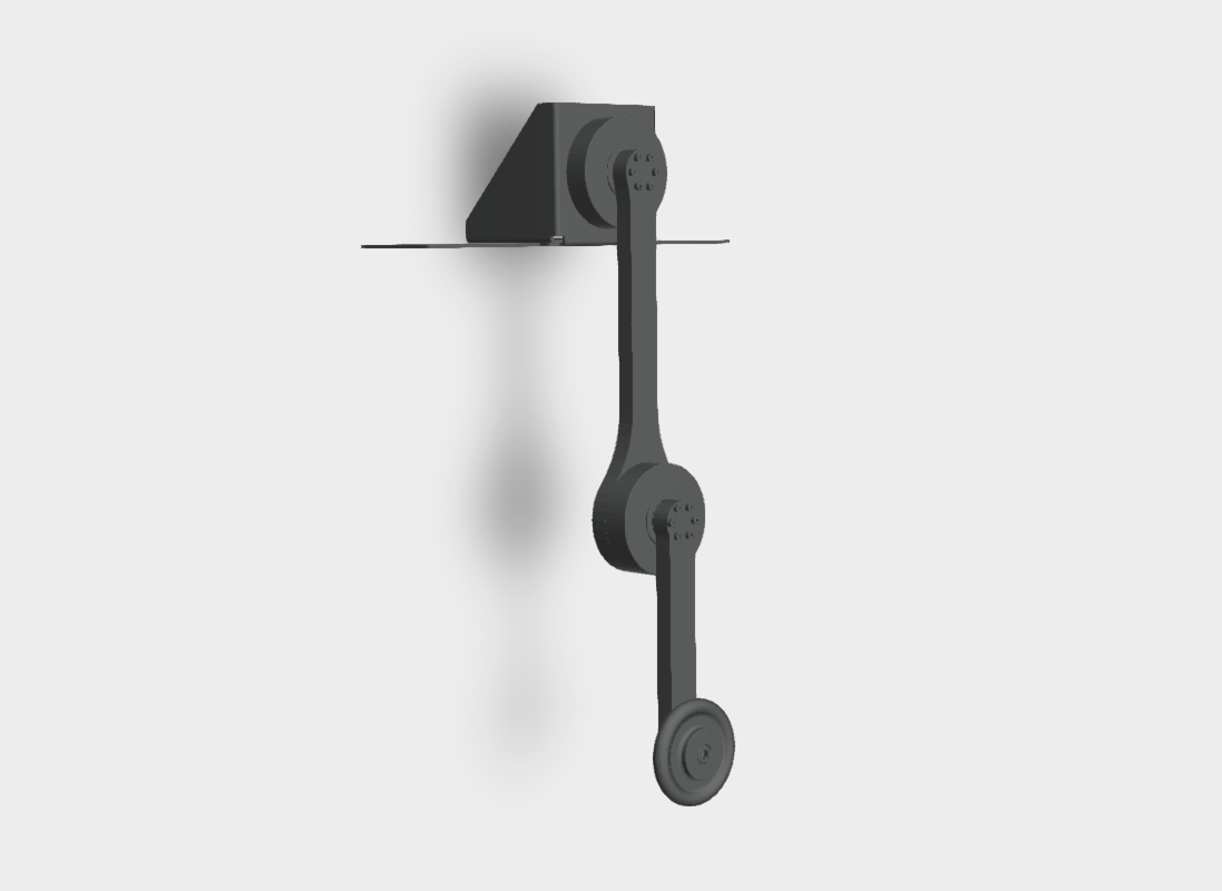
The mechanical design consists of a shoulder motor mounting bracket built with folded aluminum, and two light-weight links. The links are built either with laser cut 1 mm thick sandwich aluminum plates or with milled carbon fiber sandwich panels, and they are filled with a laminate of 15 mm PVC rigid foam board (Airex). By using these materials, the weight of the pendulum arms can be kept very low in relation to the drives and the end effector weight. The end of the first link contains the elbow motor housing and the end of second link mounts the weight. Since, the used motors do not provide a hollow shaft, the first link is mechanically extended in the opposite direction to prevent windup of cables.