T-Motor (AK-80-6)
The T-Motor double pendulum uses the AK80-6 Motors from T-Motor. Here the motors’ physical parameters, the initial setup as well as the usage with the python driver is documented. The AK80-6 manual can be found here .
Physical Parameters of the Actuator
The AK80-6 actuator from T-Motor is a quasi direct drive with a gear ratio of \(\small{6:1}\) and a peak torque of \(\small{12\,Nm}\) at the output shaft. The motor is equipped with an absolute \(\small{12}\) bit rotary encoder and an internal PD torque control loop. The motor controller is basically the same as the one used for MIT Mini-Cheetah, which is described in the documentation from Ben Katz. - Ben Katz: MIT Mini-Cheetah Documentation
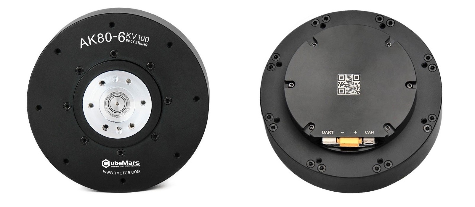
Voltage = \(\small{24\,V}\)
Current = rated \(\small{12\,V}\), peak \(\small{24\,V}\)
Torque = rated \(\small{6\,Nm}\) , peak \(\small{12\,Nm}\) (after the transmission)
Transmission \(\small{N = 6 : 1}\)
Weight = \(\small{485\,g}\)
Dimensions = \(\small{⌀\,\,98\,mm\times\,38.5\,mm}\).
Max. torque to weight ratio = \(\small{24\,\frac{Nm}{Kg}}\) (after the transmission)
Max. velocity = \(\small{38.2\,\frac{rad}{s}}\) = \(\small{365\,rpm}\) (after the transmission)
Backlash (accuracy) = \(\small{0.15°(degrees)}\)
The T-Motor Ak-80-6 has the following motor constants (before the transmission):
Motor constant \(\small{k_m = 0.2206 \,\frac{Nm}{\sqrt{W}}}\)
Electric constant \(\small{k_e = 0.009524 \,\frac{V}{rpm}}\)
Torque constant \(\small{k_t = 0.091 \,\frac{Nm}{A}}\)
Torque = rated \(\small{1.092\,Nm}\), peak \(\small{2.184\,Nm}\)
Velocity / back-EMF constant \(\small{k_v = 100 \,\frac{rpm}{V}}\)
Max. velocity at \(\small{24\,V}\)= \(\small{251.2 \,\frac{rad}{s}}\) = \(\small{2400 \,\,rpm}\)
Motor wiring in \(\small{\nabla- configuration}\)
Number of pole pairs = \(\small{21}\)
Resistance phase to phase = \(\small{170\pm5\,m\Omega}\)
Inductance phase to phase = \(\small{57\pm10\,m\mu H}\)
Rotor inertia \(\small{Ir = 0.000060719\,Kg.m^2}\)
Initial Motor Setup
The R-LINK Configuration Tool is used to configure the AK80-6 from
T-Motors. Before starting to use the R-Link device make sure you have
downloaded the CP210x Universal Windows Driver from silabs. If this
isn’t working properly follow the instructions at sparkfun on how to
install ch340 drivers. You have to download the CH 341SER (EXE) file
from the sparkfun webpage. Notice that you first have to select
uninstall in the CH341 driver menu to uninstall old drivers before you
are able to install the new driver. The configuration tool software for
the R-LINK module can be downloaded on the T-Motors website.
Tutorials
Skyentific: https://www.youtube.com/watch?v=HzY9vzgPZkA
Instructions: R-Link Config Tool
User manual & configuration tool: store-en.tmotor.com
R-LINK is a USB to serial port module, specially designed for CubeMars A Series of dynamical modular motors. It is possible to calibrate the encoder in the module, change CAN ID settings, PID settings, as well as to control position, torque and speed of the motor within the configuration software tool.
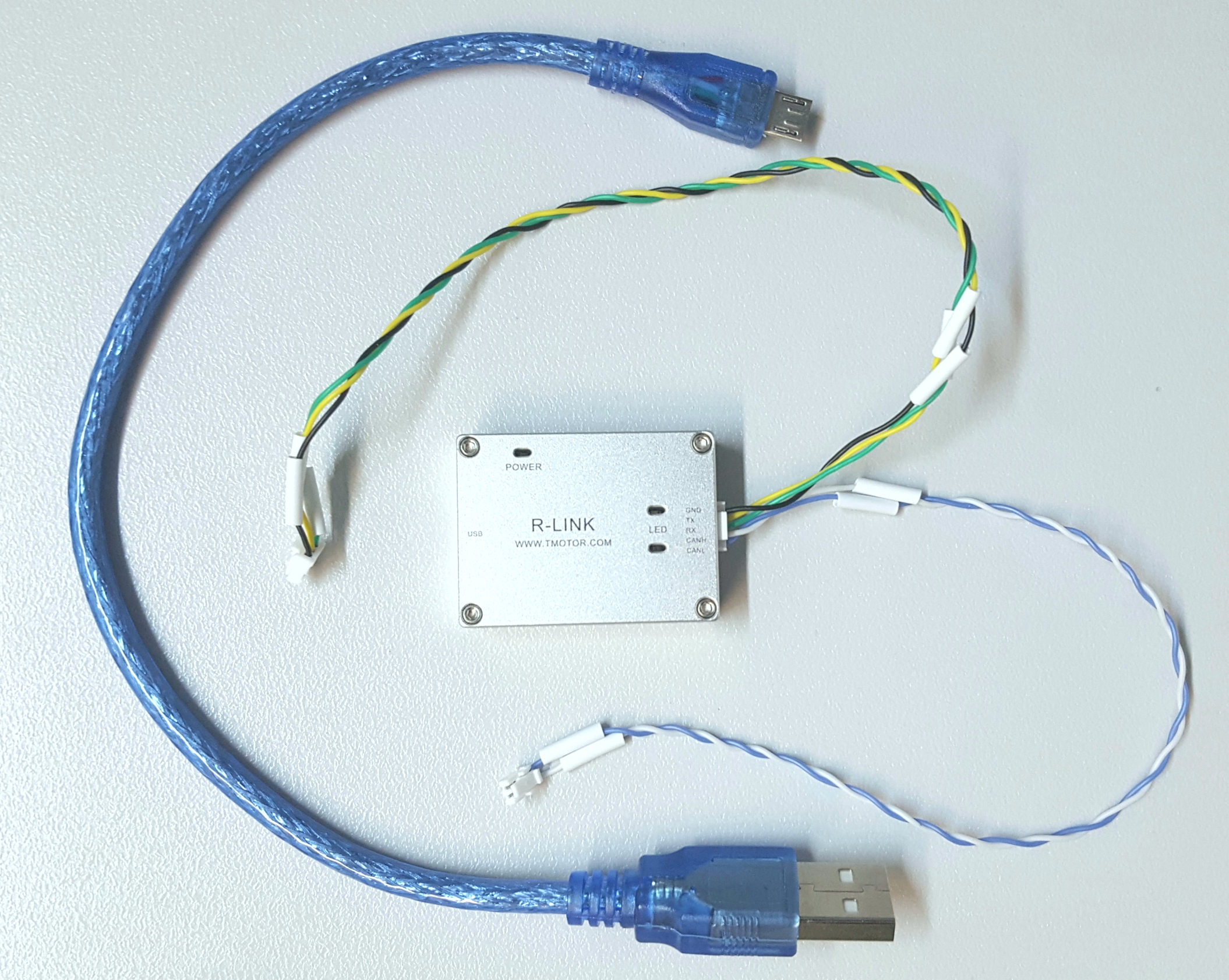
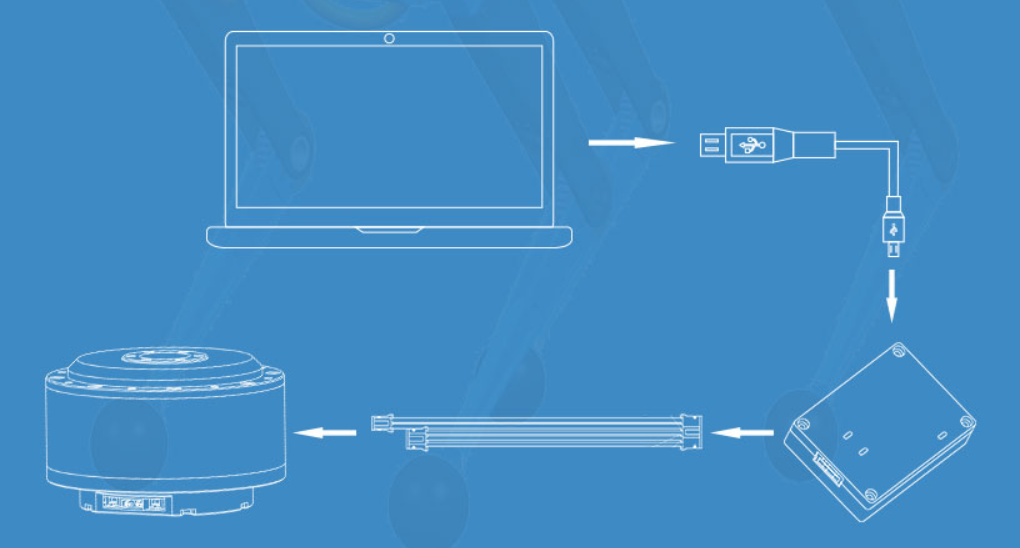
Wire the R-LINK module as shown in the figure below. A USB to micro USB cable connects a pc with the R-LINK module and the 5pin cable goes between the R-LINK module and the Motor.
Connect the AK80-6 motor to a power supply (24V, 12A) and do not cut off the power before the setting is completed.
Start the R-Link Config Tool application (only runs on Windows).
Select serial port: USB-Serial_CH340,wch,cp along with an appropriate baud rate (both 921600 and 115200 Bd should work). If the serial port option USB-Serial_CH340,wch,cp does not show up, your pc can’t establish a connection to the R-LINK module due to remaining driver issues.
Choose the desired motor settings on the left side of the config tool GUI. Enter the correct CAN ID of the motor under
MotorSelectEnter. A label on the motor shows the ID.Velocity: 5 rad/s is a relatively slow speed of revolution, hence it offers a good starting point.
Torque: be careful setting a fixed torque, because the friction inside the motor decreases with the speed of revolution. Therefore a fixed torque commonly leads to either no movement at all or accelerates the motor continuously.
Start the plotting by ticking the boxes of position, velocity, torque and select
DisplayPress
Runto start recording the plots.Enter M_Modeto control the motor. This is indicated by a color change of the plot line, from red to green.In order to push changes in the settings to the motor, press
Send Once.Warning
This button does not work reliably. Usually it has to be activated several times before the setting changes actually apply on the motor.
Stop the motor inside the M-Mode by setting the velocity to 0 and pressing
Send Onceuntil the changes apply.Exit M_Modeto exit the control mode of the motor.Warning
The next time you start the motor control with
Enter M_Modethe motor will restart with the exact same settings as you left the control mode withExit M_Mode. This is especially dangerous if a weight is attached to the pendulum and the motor control was left with high velocity or torque settings.Use
Stopto deactivate the plotting.
Debugging
Error messages that showed up during the configuration procedure, such
as UVLO (VM under voltage lockout) and OTW (Thermal warning and
shutdown), could be interpreted with the help of the data sheet for the
DRV8353M 100-V Three-Phase Smart Gate Driver from Texas Instruments:
Communication
CAN Bus wiring
Along the CAN bus proper grounding and ideally, isolated ground is required for improvement of the signal quality. Therefore, the common shared ground for PC and motors is of great importance in CAN connection communication. When daisy-chaining multiple actuators, one can use the Ground form the R-Link connector of the motor, which is connected to the negative power pin. This can share the common ground from the PC side and power supply. At the very beginning and end of the CAN chain, there must be of the termination resistors of \(\small{120\,\Omega}\) between CAN-High and CAN-Low, which will be then connected to the corresponding pins between drivers. These resistors aim to absorb the signals and prevents the signals from being reflected at the wire ends. The CAN protocol is differential, hence no additional ground reference is needed. The diagram below displays the wiring of the CAN bus.

Fig. 2: main pc = CPU, CAN transceiver = CAN XCVR, actuator = AC
Setting up the CAN interface
During regular operation the motors are commanded via CAN interface. To setup the CAN connection follow these steps:
Run this command in the terminal to make sure that
can0(or any other can interface depending on the system) shows up as an interface after connecting the USB cable to your PC:
ip link show
Configure the
can0interface to have a 1 Mbaud communication frequency:
sudo ip link set can0 type can bitrate 1000000
To bring up the
can0interface, run:
sudo ip link set up can0
Note
Alternatively, one could run the shell script
setup_caninterface.sh which will do the job for you.
Note
To change motor parameters such as CAN ID or to calibrate the
encoder, a serial connection is used. The serial terminal GUI used on Linux
for this purpose is cutecom
Testing Motor Connection
To test the connection to the motors, you can use the performance profiling script. The script will print the communication frequencies to the terminal.
Python Interface
The Python - Motor communication is done with the python driver. The basic python interface is the following:
Example Motor Initialization (for can interface can0 and motor_id =1):
motor = CanMotorController(can_socket='can0', motor_id=1, socket_timeout=0.5)
Available functions:
pos, vel, tau = motor.enable_motor()
pos, vel, tau = motor.disable_motor()
pos, vel, tau = motor.set_zero_position()
pos, vel, tau = motor.send_deg_command(position_in_degrees, velocity_in_degrees, Kp, Kd, tau_ff)
pos, vel, tau = motor.send_rad_command(position_in_radians, velocity_in_radians, Kp, Kd, tau_ff)
All functions return current position, velocity, torque in SI units
except for send_deg_command, which returns degrees instead of radians.
Internal PD-Controller
A proportional-derivative controller, which is based on the MIT Mini-Cheetah Motor, is implemented on the motor controller board. The control block diagram of this closed loop controller is shown below. It can bee seen that the control method is flexible, as pure position, speed, feed forward torque control or any combination of those is possible.
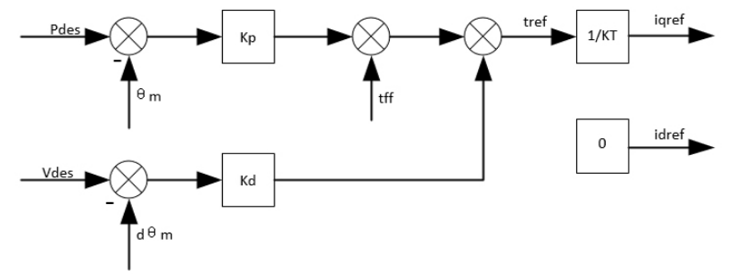
In the python driver , the:
send_rad_command(Pdes, Pvel, Kp, Kd, tff)
function lets you set desired position (Pdes), velocity (Pvel), Kp, Kd and feed forward torque (tff) values at every time step.